Deforming 3D shapes in real time, for the algebraically challenged
I recently went down a computer graphics rabbit hole after trying to render some weird shapes. It turns out that for the specific problem I was trying to solve, no existing options perfectly fit what I was trying to do. I've finally surfaced again with some answers, a few weeks and many lines of code later! I will now drag you, dear reader, along for the ride.
The goal
Basically, I wanted to take a 3D shape and animate it distorting in WebGL. Specifically, I want to combine one of each of these three things:
- An input shape: e.g. a plane, a sphere, a 3D model from a file, etc.
- A distortion function: given a point in space, tell me how much to offset that point by
- A material: render the shape with any lighting model (Is it shiny? Is it coloured with a rainbow gradient?)
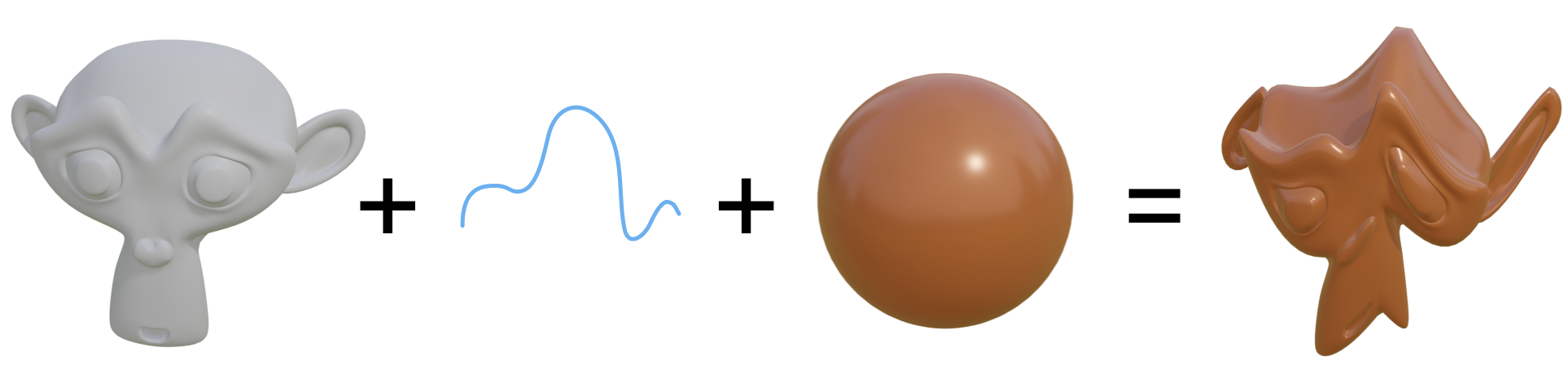
Shape + distortion + material = an endless time sink!
Why do I want this? Mostly because it looks cool, but also because it would be a really flexible framework for creative coding. Different combinations of input shapes + distortion functions + materials can lead to a really wide variety of visual results. Doing it live in WebGL as opposed to doing this with Blender nodes means it can be interactive, too, which is a plus.
I don't just want it to work in WebGL, though. I want it to work with p5.js, an incredibly versatile web graphics library. It is more limited than something like three.js for 3D tasks, but it makes interop between 2D and 3D canvases much easier. However, p5 does not provide an API for passing additional vertex attributes in with your mesh. It can be done by hooking into the underlying WebGL calls directly, but an ideal solution for me can only make use of the standard information provided in the vertex shader: positions, normals, texture coordinates, and object/camera transformation matrices.
So what's the problem?
It turns out it's pretty hard to take any shape + any distortion function and have it also work with any material. The problem has to do with surface normals. Let's have a quick refresher on what those are and why they're important.
Rendering using normals
In a typical WebGL rendering pipeline, you send shape information through a vertex shader and then through a fragment shader before an image arrives on your screen. The vertex shader processes each vertex in your shape, computing where on the screen it ends up and some other properties, such as a texture coordinate for that point, and also the normal, which is the direction pointing away from the surface at that point. Inside of each triangle of your mesh, these properties are automatically interpolated for every pixel from the properties at each corner, and get sent to the fragment shader, where they are used to find a colour for the pixel.
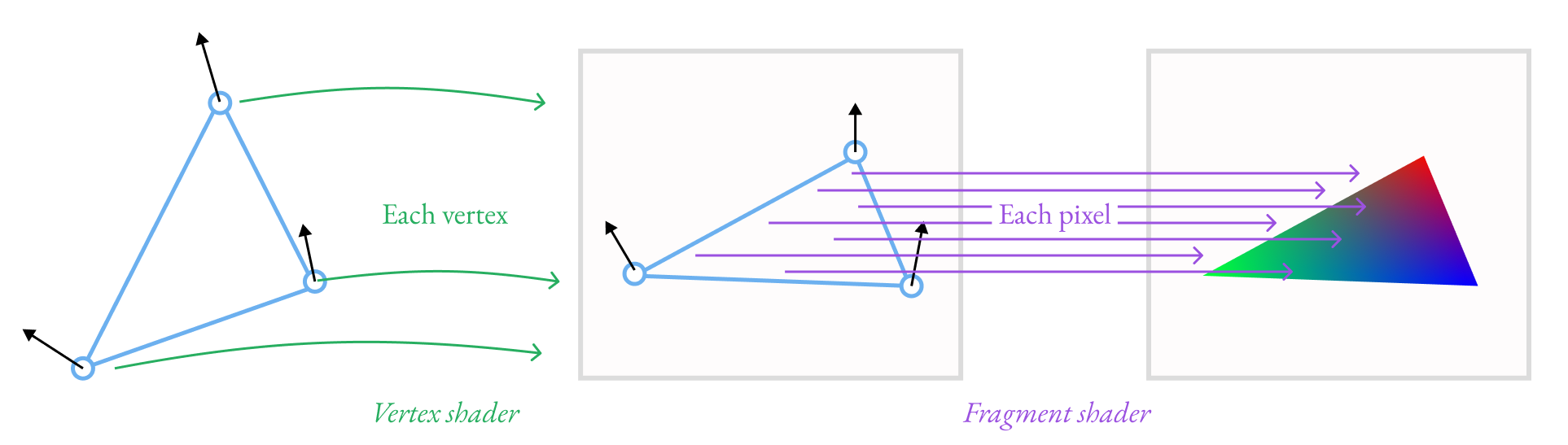
Vertices are placed at locations on the screen via the vertex shader, and the fragment shader calculates a colour for each pixel between those vertices.
In the fragment shader, the normal is important for figuring out shading. The brightness of the material's base colour depends on whether or not the surface is facing the light: if it is pointing directly at the light, it receives full direct light; as it turns away, it receives less and less light until it is facing 90 degrees away or more, at which point it receives no direct light. The normal tells us what direction the surface is facing, so we use it to perform this computation. We also use the normal when a surface is reflective, as it tells us the orientation of the surface and therefore how the light should bounce off of it.
Normals after distortion
3D models typically come with normals precomputed for each vertex, and the vertex shader doesn't need to do much to them. If the object has been rotated in the scene, maybe it needs to apply that same rotation to the normal, but other than that, it just passes it along to the fragment shader.
Unfortunately, things are more complicated when you are distorting a shape instead of just rotating it rigidly. Imagine taking a flat plane, and then distorting it with a sine wave. The undistorted plane has normals all facing the same direction. The distorted plane now has surfaces pointing in lots of different directions depending on where on the wave they fall.
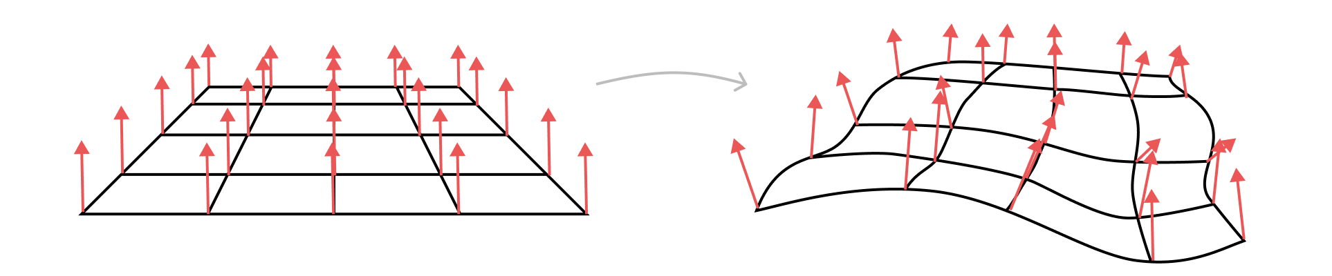
After distorting the vertices in a mesh, the original normals may no longer be correct
We can visualize the effect of this. Here we have two shapes, with unchanged normals on the left and changed normals on the right. The colours here represent the direction it thinks the surface is pointing: red means it is pointing left/right, green means it is pointing up/down, and blue means it is facing into/out of the screen.
If you ignore the changes to the normals due to distortion, shading looks noticeably wrong. If you click and drag around, you can see that the reflections on the unchanged normal blob on the left don't follow the bumps in quite the same way that they are supposed to.
Easy fixes that don't work
So we know we have to do something with the normals. What options do we have?
Automatic fragment shader derivatives
The core problem is that the normals being sent in from the vertex shader are wrong. So what if we ignore them and try to figure out the normal entirely in the fragment shader?
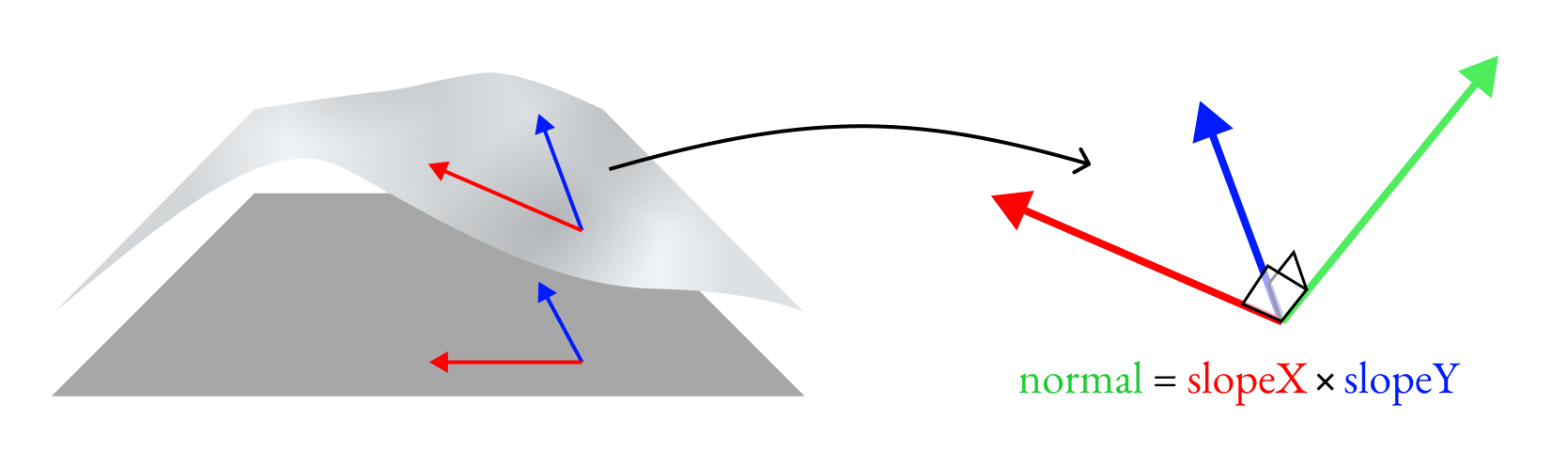
The surface normal can be found using the cross product of two surface tangents. If the surface position \(p\) can be somehow parameterized by two variables \(u\) and \(v\), then the surface normal is:
\(\vec{n} = \frac{\partial p}{\partial u} \times \frac{\partial p}{\partial v}\)
Conveniently, in the fragment shader, we can parameterize the surface position by its pixel location in x and y! GLSL provides the functions dFdx(some_variable) and dFdy(some_variable), which peek at the value of a variable in the adjacent pixel horizontally and the adjacent pixel vertically and tells you by how much its value has changed. By using these functions on the position variable, we can get the slope of the surface in two directions. Each slope is a vector tangent to the surface along the x or y axis. We can compute the surface normal as their cross product:
attribute vec3 position;
uniform vec3 baseColor;

void main() {
  vec3 normal = normalize(cross(dFdx(position), dFdy(position)));

  // Now use the normal for lighting, e.g. Lambertian diffuse shading
  vec3 toLight = vec3(0.0, 0.0, 1.0);
  float brightness = max(dot(normal, toLight), 0.0);
  gl_Fragcolour = vec4(brightness * baseColor, 1.0);
}
So far so good! But we have a problem in the result. Here is what it looks like if we colour the shape using the normal direction as its colour:
The faceted shading we're seeing is due to the normals not changing smoothly over the surface. The normals don't change smoothly because the surface itself is not actually smooth: it's made of triangles, and it's from these triangles that we are getting the normal. The surface only looked smooth before because the WebGL pipeline was interpolating the normals sent from the vertex shader for each pixel on each triangle. We don't get that smooth normal interpolation here since we're recomputing the normal ourselves.
Manual vertex shader derivatives
OK, so if we want smooth interpolation of normals on the way to the fragment shader, we need to compute the normals in the vertex shader. We want to do basically the same thing as we attempted before, getting the cross product of two surface tangents, but in the vertex shader this time.
However, in the vertex shader, we don't have the dFdx and dFdy functions any more! If we want derivatives, we have to write them ourselves!
This isn't inherently a problem. No technical limitation is preventing us from writing derivatives of our distortion function that we can then use to compute an adjusted normal. The limitation is sitting in between my keyboard and my chair. When, as an icebreaker activity, people ask me what superpower I would want, my go-to answer is that I'd like the ability to do algebra correctly the first time, every time. Unfortunately, I don't have this superpower, so when I have to program the derivative for a relatively complex distortion function, I will forget a minus sign somewhere, and I will waste hours debugging it. So for that reason, I'm going to veto calling this a "solution."
The nuclear option: auto-generating shader code
I'm vetoing writing derivatives by hand not because calculating derivatives is an art, but rather, because it's actually a rather rigid algorithm that must be followed, and my fallible human brain is not good at following rigid algorithms. But you know what is good at following rigid algorithms? A computer. So what if we tasked the computer with writing our derivatives?
Architecture for automatic differentiation
Computing the derivative of a function with respect to some variable is a fairly straightforward recursive algorithm. It's one that you probably learned in high school. Every basic operation has a predefined derivative. For example, \(\frac{\partial}{\partial x} \sin(x) = \cos(x)\). If an operation is being applied to some more complicated function \(u\), then we use the recursive chain rule, where we multiply the derivative of a sine operation by the derivative of whatever \(u\) happens to be: \(\frac{\partial}{\partial x} \sin(u) = \cos(u) \frac{\partial u}{\partial x}\). You just keep working your way deeper, from the outermost operation inward, until you can't break down \(u\) any further.
Modeling this in an object-oriented way, every operation will be an object that knows how to compute its own derivative. Its parameters may themselves be operations with derivatives. An expression like 0.1 * (sin(10*x + 20))^2 would translate into an object hierarchy like this:

A syntax tree breakdown of 0.1 * (sin(10*x + 20))^2
An implementation for a sin operation might look something like this, where it contains methods to generate code representing its value and also code representing the value of its derivative, both of which recursively call functions on its parameter:
class Sin {
  constructor(u) {
    this.u = u;
  }

  code() {
    return `sin(${u.code()})`
  }

  derivativeCode() {
    `cos(${u.code()}) * ${u.derivativeCode()}`
  }
}
You could then use it in a shader by splicing in the output of derivativeCode():
const sinOp = new Sin( /* TODO build up tree of operations here */ );
const vert = `
  uniform mat4 uModelViewMatrix;
  uniform mat4 uProjectionMatrix;
  attribute vec3 position;

  void main() {
    vec3 newPosition = position;
    newPosition.y += ${sinOp.code()};

    float deriv = ${sinOp.derivativeCode()};
    // TODO do something with deriv here

    gl_Position = uProjectionMatrix * uProjectionMatrix * vec4(newPosition, 1.0);
  }
`;
Then, if you write the code you want a derivative of by building up a tree of operations, you also can generate code to calculate derivatives for free!
Of course, writing your code by constructing objects representing every operation can be tedious. I know this firsthand: an early prototype for a fourth year design project idea from my undergrad years at Waterloo had me doing this, and it is one of the main reasons why we abandoned that project idea. One option might be to have you write GLSL code as a string, parse the string into a syntax tree, and then map each node in the syntax tree to an operation. This option is nice, but it is a decent amount of work to implement. As a compromise, I instead opted to use a Builder-like design pattern with chainable methods to make writing less verbose. Since the operation objects are also normal Javascript objects, they can also be assigned and reassigned in loops and conditionals (any Javascript code used acts like a macro from the perspective of the generated GLSL.)
The library I created is available on NPM as @davepagurek/glsl-autodiff. It's also what's powering the "proper normals" examples on this page! It lets you write some expressions and then take the derivative of those expressions with respect to your input variables. Here's a snippet of what it looks like to use the final library:
import { gen } from '@davepagurek/glsl-autodiff';

const vert = `
  void main(void) {
    vec4 objSpacePosition = vec4(aPosition, 1.0);

    float x = objSpacePosition.x;
    float y = objSpacePosition.y;
    ${gen((ad) => {
      const x = ad.param('x');
      const y = ad.param('y');
      const time = ad.param('time');
      const speedX = 1.5;
      const speedY = 2.8;

      let offset = ad.val(0);
      for (let i = 0; i < 3; i++) {
        offset = offset.add(ad.sin(
          ad.sum(
            offset.mult(0.5).add(x.mult(speedX)).add(y.mult(speedY)),
            time.mult(0.002),
          )
        ));
      }
      offset = offset.mult(0.1);
      offset.output('z');
      offset.outputDeriv('dzdx', x);
      offset.outputDeriv('dzdy', y);
    })}
    objSpacePosition.z = z;
    vec3 tangentX = vec3(1.0, 0.0, dzdx);
    vec3 tangentY = vec3(0.0, 1.0, dzdy);
    vNormal = uNormalMatrix * normalize(cross(tangentX, tangentY));

    vec4 worldSpacePosition = uModelViewMatrix * objSpacePosition;
    gl_Position = uProjectionMatrix * worldSpacePosition;
  }
`;
What do we actually do with these derivatives?
Great, we can now write a distortion function and get derivatives automatically. What do we do with those derivatives to get the normals we've been so desperately looking for?
First steps: deforming a plane
I started out with a simple but still practical case: distorting a plane in one dimension. Given an x and y position on the plane, I'll supply a function that generates a new z value. This setup is a nice starting point because we can easily come up with two surface tangents by getting the derivatives in x and y, like we did in the fragment shader. Using glsl-autodiff, we can splice the following into the vertex shader to get both the displacement and its derivatives in x and y:
gen((ad) => {
  const position = ad.vec3Param('position');

  // Imagine we have a displace() function, generating offset based on x and y
  const offset = displace(position.x(), position.y());

  offset.output('offset');
  offset.outputDeriv('doffset_by_dx', position.x());
  offset.outputDeriv('doffset_by_dy', position.y());
})
Now we need to get the surface normal from that. If the original position on the surface of a plane is \(p\) and our new offset is \(k\), our distorted position is \(p' = p + \begin{bmatrix}0&0&k\end{bmatrix}^T\). Since our input is a plane, we also know that the derivatives of the original position with respect to x and y are fairly simple (in this case, the x and y derivatives are just unit vectors pointing respectively in the x or y directions). The math for the normal works out to the following:
\(\begin{aligned}\vec{n} &= \frac{\partial p'}{\partial x} \times \frac{\partial p'}{\partial y}\\&= \frac{\partial(p+\begin{bmatrix}0&0&k\end{bmatrix}^T)}{\partial x} \times \frac{\partial(p+\begin{bmatrix}0&0&k\end{bmatrix}^T)}{\partial y}\\&= \left(\frac{\partial p}{\partial x} + \begin{bmatrix}0&0&\frac{\partial k}{\partial x}\end{bmatrix}^T\right) \times \left(\frac{\partial p}{\partial y} + \begin{bmatrix}0&0&\frac{\partial k}{\partial y}\end{bmatrix}^T\right)\\&= \left(\begin{bmatrix}1&0&0\end{bmatrix}^T + \begin{bmatrix}0&0&\frac{\partial k}{\partial x}\end{bmatrix}^T\right) \times \left(\begin{bmatrix}0&1&0\end{bmatrix}^T + \begin{bmatrix}0&0&\frac{\partial k}{\partial y}\end{bmatrix}^T\right)\\&= \begin{bmatrix}1&0&\frac{\partial k}{\partial x}\end{bmatrix}^T \times \begin{bmatrix}0&1&\frac{\partial k}{\partial y}\end{bmatrix}^T\\\end{aligned}\)
Since the displacement directly gives us two surface tangent vectors, we can get a normal easily by crossing them.
Here's how that looks in the rest of the shader, making use of the autodiff output variables doffset_by_dx and doffset_by_dy:
// Use the offset
vec3 outPosition = position;
outPosition.z += offset;

// The normal is the cross product of two surface tangents, which are
// the changes in z given a unit change in our two surface directions
vec3 tangentX = vec3(1., 0., doffset_by_dx);
vec3 tangentY = vec3(0., 1., doffset_by_dy);
vec3 normal = normalize(cross(tangentX, tangentY));
Deforming a shape that has existing normals
Things get a little more complicated when you use the same x, y => z displacement on an input shape that wasn't flat to start with. A plane happens to be easily parameterized by x and y, letting us easily get directional derivatives, but any arbitrary input shape might not be.
Perusing the Wikipedia article on computing surface normals isn't much help because it's mostly concerned with shapes defined by functions. If we had a function defining the full shape, we could take the derivative of that function with respect to two parameters. But inside a vertex shader, we can make no assumptions about the shape of the surface beyond two pieces of information: the position of the current vertex and its existing normal. We only have a function for the displacement of the shape. A 2010 paper by Morten Mikkelsen comes close: it describes how to compute normals for arbitrary bump maps on arbitrary surfaces, but only for bump maps that deform surfaces in the direction of the surface normal by variable amounts. In our case, our displacement direction may be completely unrelated to the surface normal direction.
The solution I came to is to compute the rotation of the normal induced by the displacement, and then apply that to the input normal. For a given position, imagine we started with a flat plane and then distorted that plane. We know the plane's normal started by pointing in the z direction, and then ended up pointing in the direction cross(tangentX, tangentY). We can calculate the rotation between those two vectors, and then apply the same rotation to the original normal of our non-plane mesh!
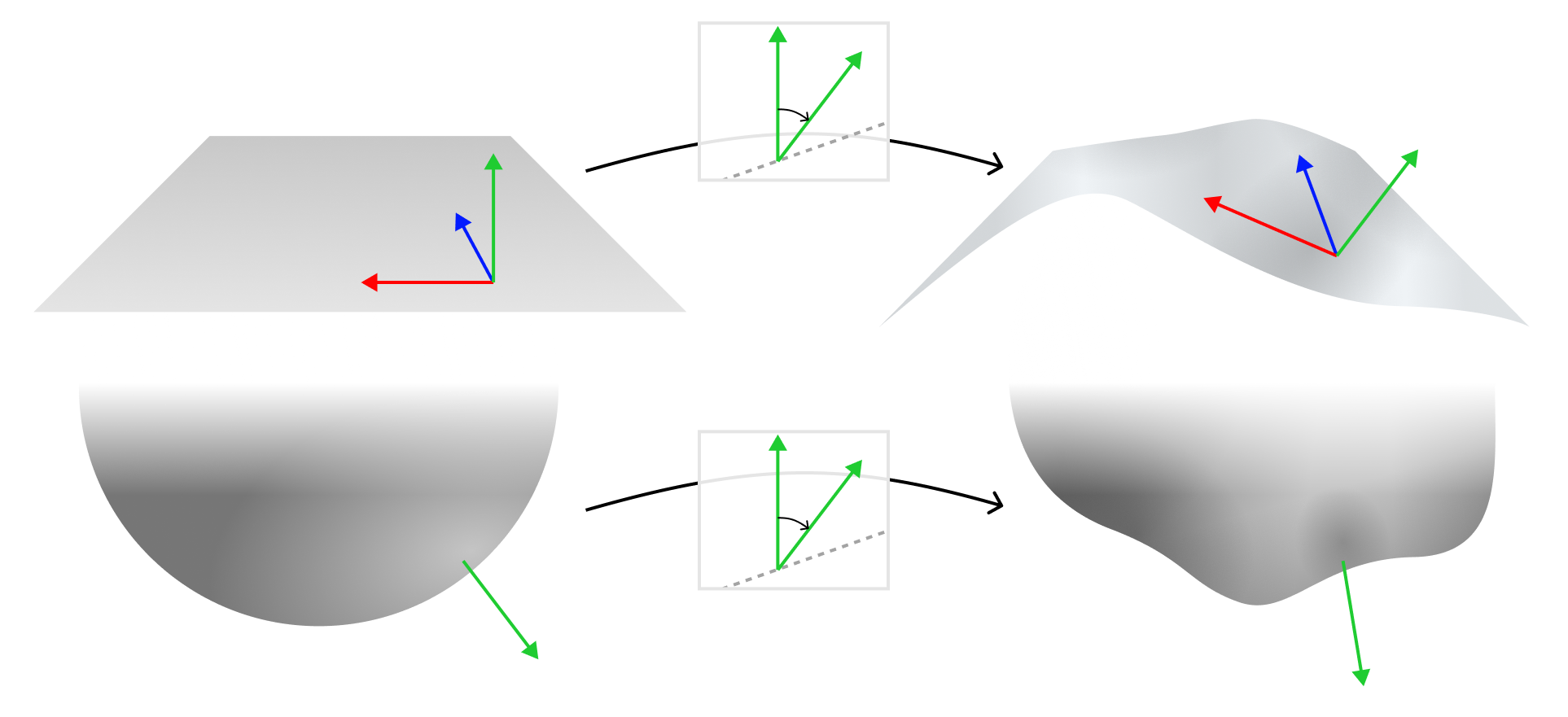
If we imagine a plane being deformed, we can calculate the rotation on the normal induced by the deformation. We can then apply that same rotation to the initial surface normal of any other shape.
The angle between any two vectors \(\vec{v}_1\) and \(\vec{v}_2\) is \(\cos^{-1}(\vec{v}_1 \cdot \vec{v}_2)\). The axis of rotation in this case will be a vector perpendicular to the two input vectors, which we can get by doing \(\vec{v}_1 \times \vec{v}_2\). Using this axis and angle, we can construct a rotation matrix that will apply the same rotation to any vector you multiply it by. Here's how that looks in GLSL:
// Assume we have a function to generate an axis/angle rotation matrix:
mat4 axisAngleRotation(vec3 axis, float angle) { /* ... */ }
// See http://www.neilmendoza.com/glsl-rotation-about-an-arbitrary-axis for an implementation

// Compute a normal like before, as if the mesh were a plane
vec3 tangentX = vec3(1., 0., doffset_by_dx);
vec3 tangentY = vec3(0., 1., doffset_by_dy);
vec3 displacedPlaneNormal = normalize(cross(tangentX, tangentY));

// The un-displaced normal for our hypothetical plane. This is the result
// of crossing the undistorted surface normals: cross(vec3(1.,0.,0.), vec3(0.,1.,0.))
vec3 originalPlaneNormal = vec3(0., 0., 1.);

// Find the rotation induced by the displacement
float angle = acos(dot(originalPlaneNormal, noDisplacementNormal));
vec3 axis = normalize(cross(originalPlaneNormal, noDisplacementNormal));
mat4 rotation = axisAngleRotation(axis, angle);

// Apply the rotation to the original normal
vec3 normal = (rotation * vec4(origNormal, 0.)).xyz;
Deforming a shape in three dimensions
The final leap we need to make is to support distortions in more than just the z axis, taking the full vertex position as input and generating a full 3D vector as output (which I will refer to as \(\vec{k}\) as opposed to the scalar \(k\) we had previously).
Since we need to get the cross product of two surface tangents, we will again need two directional derivatives. Previously, since the distortion only depended on x and y, the obvious axes to use for our directional derivatives are x and y. But since we now depend on x, y, and z, we need our derivatives to take into account all three. One way of addressing this is to use x and \(u\) as axes, where we define \(u = y + z\).
To get the derivative with respect to \(u\), we can look at the Jacobian of our displacement function, where \(J = \begin{bmatrix}\frac{\partial \vec{k}}{\partial x} & \frac{\partial \vec{k}}{\partial y} & \frac{\partial \vec{k}}{\partial z}\end{bmatrix}\), and each of those partial derivatives gives us a column vector now that the displacement \(\vec{k}\) is a 3D vector. The dot product of the Jacobian matrix with a direction vector gives us the directional derivative for that direction vector. In our case, the derivative with respect to \(u\) ends up just being the sum of the y and z derivatives:
\(\begin{aligned}\frac{\partial \vec{k}}{\partial u} &= J \cdot \vec{u}\\&= J \cdot \begin{bmatrix}0&1&1\end{bmatrix}^T\\&= \begin{bmatrix} \frac{\partial k_x}{\partial y} + \frac{\partial k_x}{\partial z}\\ \frac{\partial k_y}{\partial y} + \frac{\partial k_y}{\partial z}\\ \frac{\partial k_z}{\partial y} + \frac{\partial k_z}{\partial z}\\\end{bmatrix}\\&= \frac{\partial \vec{k}}{\partial y} + \frac{\partial \vec{k}}{\partial z}\\\end{aligned}\)
Now we can use this to do the math to get the normal. The plane's derivative with respect to \(u\) is simple again, it's just \(\begin{bmatrix}0&1&1\end{bmatrix}\). The normal works out to the following:
\(\begin{aligned}\vec{n} &= \frac{\partial p'}{\partial x} \times \frac{\partial p'}{\partial u}\\&= \frac{\partial(p+\vec{k})}{\partial x} \times \frac{\partial(p+\vec{k})}{\partial u}\\&= \left(\frac{\partial p}{\partial x} + \frac{\partial \vec{k}}{\partial x}\right) \times \left(\frac{\partial p}{\partial y} + \frac{\partial \vec{k}}{\partial u}\right)\\&= \left(\begin{bmatrix}1&0&0\end{bmatrix}^T + \frac{\partial \vec{k}}{\partial x}\right) \times \left(\begin{bmatrix}0&1&1\end{bmatrix}^T + \frac{\partial \vec{k}}{\partial y} + \frac{\partial \vec{k}}{\partial z}\right)\\\end{aligned}\)
I justify to myself that this is consistent with our 1D deformation normals because, previously, our slope vectors had the form an axis vector plus the displacement due to a change in that axis. Previously our displacement happened to be in an axis orthogonal to our direction, such as the x axis slope \(\begin{bmatrix}1&0&0\end{bmatrix}^T + \begin{bmatrix}0&0&\frac{\partial k}{\partial x}\end{bmatrix}^T\). It just so happens that, now, our displacement vector might have nonzero components in our direction vector's axes, but we still have the same form: \(\begin{bmatrix}1&0&0\end{bmatrix}^T + \frac{\partial \vec{k}}{\partial x}\).
The GLSL version of this calculation looks fairly similar to before:
// doffset_by_d{x,y,z} are all vec3s now instead of a floats
vec3 tangentX = vec3(1., 0., 0.) + doffset_by_dx;
vec3 tangentYZ = vec3(0., 1., 1.) + doffset_by_dy + doffset_by_dz;
vec3 displacedPlaneNormal = normalize(cross(tangentX, tangentY));

// The un-displaced normal for our hypothetical plane
vec3 originalPlaneNormal = normalize(cross(vec3(1., 0., 0.), vec3(0., 1., 1.));

// Everything from here on is the same as before!

// Find the rotation induced by the displacement
float angle = acos(dot(originalPlaneNormal, noDisplacementNormal));
vec3 axis = normalize(cross(originalPlaneNormal, noDisplacementNormal));
mat4 rotation = axisAngleRotation(axis, angle);

// Apply the rotation to the original normal
vec3 normal = (rotation * vec4(origNormal, 0.)).xyz;
...and that's it! That's the shader code we need to get to our goal of taking arbitrary shapes, distortions, and materials and have the normals work.
Doing something with it
Now that we've built a distortion pipeline, let's actually do something with it! Since I only just got everything working (plus an additional week or two of doing the math to convince myself that what this method actually has some justified reason for working correctly) I will leave you with just one sketch using it. But expect this to be subtly included in future projects!
Here's a sketch I'm going to call Airplane! which is loosely inspired by the movie poster for the classic 1980 movie. If you want to inspect the source, you can find it on the p5 web editor.