p5.env: Generative environment lighting
A Google Summer of Code project a few years ago added the imageLight() method to p5.js. This lets you load in a sphere map image of an environment, and then use it to light your scene.
let env;
async function setup() {
  createCanvas(200, 200, WEBGL);
  env = await loadImage('/content/images/2021/07/outdoor_spheremap.jpg');
}

function draw() {
  background(255);
  orbitControl();
  imageLight(env);
  ambientLight(80);
  noStroke();
  fill(255);
  specularMaterial(100);
  shininess(50);
  torus(50, 20, 32, 24);
}
If I crank up the metalness and the shininess to make a mirror, you can see the environment more clearly. Try clicking and dragging around!
let env;
async function setup() {
  createCanvas(200, 200, WEBGL);
  env = await loadImage('/content/images/2021/07/outdoor_spheremap.jpg');
}

function draw() {
  background(255);
  orbitControl();
  imageLight(env);
  noStroke();
  fill(255);
  shininess(200);
  metalness(200);
  torus(50, 20, 32, 24);
}
Now this is great, and it's a way to get you interesting lighting quickly.
Under the hood, it's generating a few different things for you. In order to support you changing the shininess of the material, it precomputes a number of images showing the accumulated reflected light from each angle at different levels of roughness. It's like a specific kind of a blur filter. Each successively blurrier image also gets smaller in size as there is less detail to preserve. When you change the material shininess, p5 smoothly mixes between these precomputed images.
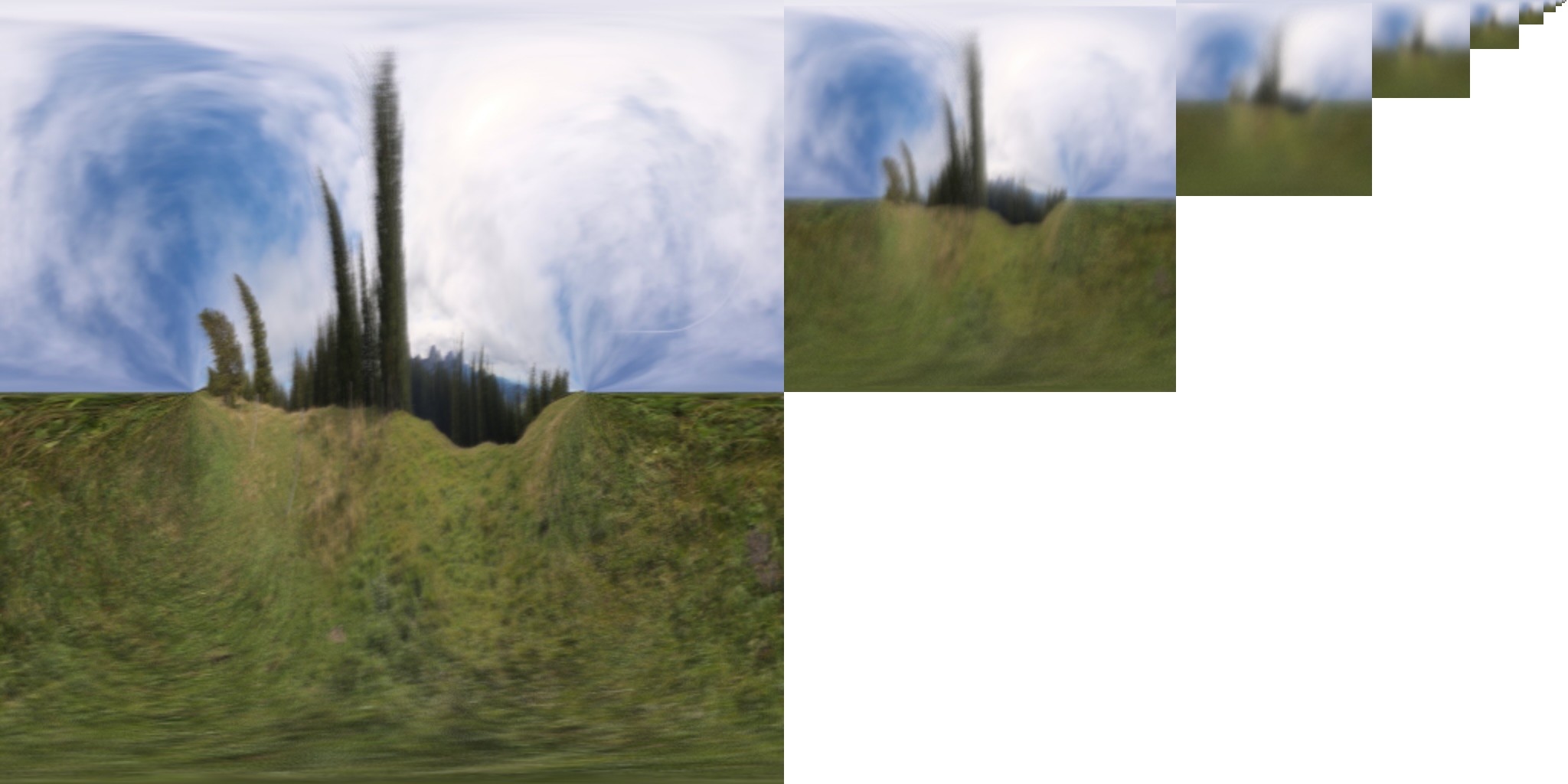
Successively blurrier reflections of the environment. In each image, the x axis corresponds to different azimuthal angles, and the y axis corresponds to different polar angles.
However, it does involve finding and loading an image. And if there's something about the look that you want to tweak, you have to go back and edit the image, and then re-upload it to your sketch. That gets pretty annoying. I'd really like to just make my own environments. The process of setting up an image for use in lighting is also pretty heavy. You might not notice it because p5 does it once upfront, but it means we can't use video for image lighting, as then you'd have to recompute it every frame. Ideally, I'd also to use a representation that would support animation.
Before imageLight was added, you had the Phong lighting model to work with. You could tweak the ambient light, and add a number of other light prototypes. That's still available! But it's quite hard to make something that feels like an environment. Let me try adding some directional lights to see if I can imitate the light from the sky and the bounced light off of the ground:
function setup() {
  createCanvas(200, 200, WEBGL);
}

function draw() {
  background(255);
  orbitControl();
  ambientLight(150);
  directionalLight('#593d3a', 0, -1, 0);
  directionalLight('#3b9de2', 0, 1, 0);
  noStroke();
  fill(255);
  specularMaterial(100);
  shininess(50);
  torus(50, 20, 32, 24);
}
...not super successful. But we do now have other tools we can reach for: shaders! Maybe we can make ourselves a system where we can create our own environment maps.
We don't need to go for realism in order to create a sense of space and a sense of belinging to a scene. So let's start with something simple: what if we had a single colour in the sky and a single colour on the ground?
We can make a shader that does not use the lighting model at all, and instead directly picks a color based on what we're looking at. The surface normal tells us what direction the surface is pointing at any given spot. We can use that to determine what colour it's looking at in the environment. Pretending it gets all its light from that one spot, we can set its material color to that. For a simple example: if the normal is pointing slightly up at all, use the sky colour; otherwise, use the ground colour.
let material;
function setup() {
  createCanvas(200, 200, WEBGL);
  material = buildMaterialShader(envLight);
}

function envLight() {
  pixelInputs.begin();
  pixelInputs.color.rgb = mix(
    [178, 214, 232] / 255,
    [104, 124, 106] / 255,
    step(0, pixelInputs.normal.y)
  );
  pixelInputs.end();
}

function draw() {
  background(255);
  orbitControl();
  noStroke();
  shader(material);
  torus(50, 20, 32, 24);
}
Now, one of the things that imageLight does for you behind the scenes is that it does an integral for you, adding up all the light that reaches a given point from all angles. It uses some specific weighting based on how much light gets contributed based on its angle, but at the end of the day, it looks like a blur. As long as we're not chasing realism, we can pretend to do a blur by using smoothstep instead of step.
let material;
function setup() {
  createCanvas(200, 200, WEBGL);
  material = buildMaterialShader(envLight);
}

function envLight() {
  pixelInputs.begin();
  pixelInputs.color.rgb = mix(
    [178, 214, 232] / 255,
    [104, 124, 106] / 255,
    smoothstep(-1, 1, pixelInputs.normal.y)
  );
  pixelInputs.end();
}

function draw() {
  background(255);
  orbitControl();
  noStroke();
  shader(material);
  torus(50, 20, 32, 24);
}
Suddenly that's starting to look like lighting! You really don't need a lot.
This is the key idea I wanted to explore: what would it look like to make a generative, codable version of p5's imageLight()?
Goals
There are two components that I'm looking for: the ability to easily and flexibly code up an environment, and the ability to quickly render it at different roughness levels.
Arguably, imageLight already comes with a solution that meets the first criterion: you can draw to a p5.Framebuffer, call .get() on it to save a p5.Image snapshot of it, and then pass that to imageLight() every frame. This would let you draw whatever you want, and then use it for lighting. It has a few drawbacks, though:
- The standard p5 cartesian coordinate system makes it hard to create seamless environments. You need to make sure content wraps on the horizontal borders, and expands at the vertical borders to avoid content appearing squeezed at the poles.
- You can't easily control lighting intensity. In theory there's nothing really stopping lights from exceeding a value of 255; in images, however, range is clamped. HDR image formats get around this, but for simplicity, imageLight() is set up to take in non-HDR images, more accessible for most people, and extracts what it thinks is a reasonable approximation of the true brightness. This compromise feels more annoying when you're manually picking colours for your lights.
- You still can't really animate this way. Generating the roughness levels is still too expensive a process to run each frame.
Fast blur with 2D signed distance functions
A signed distance function, or SDF, is a representation of a shape. It's a function that tells you, for a given input coordinate, how far away from the shape you are.
A simple example of an SDF is a circle: d = sqrt(x^2 + y^2) - r. Here's what that value looks like on a 2D plane, with blue representing negative numbers, red representing positive numbers, and white representing zero:
let sdf;
let radius;
function setup() {
  createCanvas(200, 200, WEBGL);
  createP().html('r').position(0, 185);
  radius = createSlider(0, 100, 50, 0.1).position(20, 200);
  sdf = buildFilterShader(circleSDF);
  noLoop();
  radius.input(redraw);
}

function circleSDF() {
  const r = uniformFloat(() => radius.value());
  filterColor.begin();
  let d = length((filterColor.texCoord - 0.5) * filterColor.canvasSize) - r;
  let c = mix(
    [0, 0, 1, 1],
    mix(
      [1, 1, 1, 1],
      [1, 0, 0, 1],
      map(d, 0, 100, 0, 1, true)
    ),
    map(d, -100, 0, 0, 1, true)
  );
  filterColor.set(c);
  filterColor.end();
}

function draw() {
  clear();
  filter(sdf);
}
Rather than using the visualization above, let's use this SDF to create a sun in the sky. If we're in a negative region, we'll output white. Otherwise, we'll output sky blue. Here, I'm using step(border, val) again: it returns 1 when val >= border and 0 otherwise.
let sdf;
function setup() {
  createCanvas(200, 200, WEBGL);
  sdf = buildFilterShader(circleSDF);
  noLoop();
}

function circleSDF() {
  filterColor.begin();
  let d = length((filterColor.texCoord - 0.5) * filterColor.canvasSize) - 50;
  let c = mix(
    [1, 1, 1, 1],
    [42, 161, 252, 255] / 255,
    step(0, d)
  );
  filterColor.set(c);
  filterColor.end();
}

function draw() {
  clear();
  filter(sdf);
}
Now let's use a similar trick as before: rather than having a fixed border, let's spread it out over a region to simulate a blur. Instead of step(border, val), let's linearly blend with map(val, border - blur, border + blur, 0, 1, true). As you change the blur radius below, notice how this creates an outer edge where the white fully ends, and an inner edge, where we get full white.
let sdf;
let blur;
function setup() {
  createCanvas(200, 200, WEBGL);
  createP().html('blur').position(0, 185);
  blur = createSlider(0.1, 100, 10, 0.1).position(30, 200);
  sdf = buildFilterShader(circleSDF);
  noLoop();
  blur.input(redraw);
}

function circleSDF() {
  const blurAmt = uniformFloat(() => blur.value());
  filterColor.begin();
  let d = length((filterColor.texCoord - 0.5) * filterColor.canvasSize) - 50;
  let c = mix(
    [1, 1, 1, 1],
    [42, 161, 252, 255] / 255,
    map(d, -blurAmt, blurAmt, 0, 1, true)
  );
  filterColor.set(c);
  filterColor.end();
}

function draw() {
  clear();
  filter(sdf);
}
We've got a pretty convincing blur! This is the basic technique we'll use to make any shape in the environment blurrable.
Does it tint too much?
One thing that you have to do when rendering an environment is not just blur it a little, but actually blur it a lot. Completely matte surfaces will want to blur things with a 90° radius. And the version of the blur described earlier, while certainly a good start, starts to show some issues when stretched that far. Namely, things blurred that much still show up too much. This matters because it makes it harder to create environments that look reasonable on both glossy and matte objects. Currently, small elements will accidentally dominate the overall colour on matte objects.
With a different framing: our simple blur adds energy at large blurs. Light is a form of energy. Each object in our environment outputs a specific amount of it. Blur should not change that amount; it should just spread it out.
With yet different framing: if we sum the brightness over the whole area, it should be the same blurred as unblurred. You know what that means: time to do some integrals!
Let's start by seeing what happens with zero blur. We can integrate over concentric rings until we reach the radius of the circle, \(r\). Knowing that the circumference of a circle is \(2\pi r\), and assuming the brightness at a given radius, \(W(x)\) of the unblurred circle is just 1, we get:
\(\begin{aligned}A &= \int_0^r 2 \pi x W(x) dx\\&= \int_0^r 2 \pi x dx\\&= \pi r^2\\\end{aligned}\)
Ok, that should have come as no surprise. But now let's compare that with a blurred circle with blur radius \(b\). In this case, we can split up our sum into two parts: the constant-brightness inner circle, and the gradient ring.
We can reuse the formula above for the constant part, which has a radius of \(r-b\). For the ring, it goes from brightness of 1 at the inner edge to 0 at the outer edge: \(W(x) = 1 - \frac{x - (r-b)}{2b}\). Putting that together, we get:
\(\begin{aligned}A &= \pi (r-b)^2 + \int_{r-b}^{r+b} 2 \pi x W(x) dx\\&= \pi (r-b)^2 + \int_0^r 2 \pi x \left( 1 - \frac{x - (r-b)}{2b} \right) dx\\&= \pi (r-b)^2 + \frac{\pi r^2(2b + r)}{2b}\\\end{aligned}\)
That's not quite the same, even though it would need to be if it preserved energy.
So the next question is, what would it take to make it preserve energy in this scenario? We can pick a different "family" of \(W(x)\) and try to solve for the parameters that would give us the original area. If we let \(u = \frac{x-(r-b)}{2b}\), then one such family is using exponential ease rather than linear: \(W(u) = (1 - u)^k\) for some \(k\). I should make clear that this is an arbitrary decision. You could pick a crazy sinusoidal function and still figure out how to preserve area. It comes down, essentially, to what you want your blur to look like. Here's what different values look like in that exponential family:
let sdf;
let kPower
function setup() {
  createCanvas(200, 200, WEBGL);
  createP().html('k').position(0, 185);
  kPower = createSlider(-6, 6, 0, 0.1).position(30, 200);
  sdf = buildFilterShader(circleSDF);
  noLoop();
  kPower.input(redraw);
}

function circleSDF() {
  const blurAmt = 20
  const k = uniformFloat(() => pow(2, kPower.value()))
  filterColor.begin();
  let d = length((filterColor.texCoord - 0.5) * filterColor.canvasSize) - 50;
  let c = mix(
    [1, 1, 1, 1],
    [42, 161, 252, 255] / 255,
    pow(map(d, -blurAmt, blurAmt, 0, 1, true), k)
  );
  filterColor.set(c);
  filterColor.end();
}

function draw() {
  clear();
  filter(sdf);
}
Solving for \(k\):
\(\begin{aligned}\pi r^2 &= \pi (r-b)^2 + \int_{r-b}^{r+b} 2 \pi x W(x) dx\\br-\frac{b^2}{2} &= \int_{r-b}^{r+b} x W(x) dx\\&= \int_{r-b}^{r+b} x \left(1-\frac{x-(r-b)}{2b}\right)^k dx\\&= 2b \int_0^1 (b(2u-1)+r)(1-u)^k du\\r - \frac{b}{2} &= \frac{2(r-b)}{k+1} + \frac{4b}{(k+1)(k+2)}\\\end{aligned}\)
Writing this in terms of \(\alpha = \frac{b}{r}\), the ratio of blur to the radius of the circle:
\(\begin{aligned}(1-\frac{\alpha}{2})(k+1)(k+2) &= 2(1-\alpha)(k+2)+4\alpha\\k &= \frac{\alpha + 2 \pm \sqrt{-7\alpha^2 + 4\alpha + 36}}{2(\alpha-2)}\\\end{aligned}\)
This gives us two formulas for \(k\), but we'll use the one where the \(\pm\) is just a \(-\) because it gives us \(k=1\) when \(\alpha=0\) instead of a negative number, which makes the most sense for our problem: at small blurs, an almost linear gradient should be totally sufficient. Here's what our graph of \(k\) looks like:
You may notice that it has a hole at \(\alpha=2\) and stops existing altogether past around 2.5. It turns out those don't actually matter, but only because this serves as a broader wake-up call: our formula doesn't apply when \(\alpha\) goes above 1. It's the ratio of the blur radius to the circle radius, so when it goes above 1, we no longer have an inner circle surrounded by a gradient ring, we just have a gradient circle! Increase the blur below to show how the gradient ring becomes a full circle.
A simple thing we can do at \(\alpha=1\) is freeze \(k\) where it is (which happens to be \(\frac{1}{2}(\sqrt{33}-3)\), around 1.372) and then figure out an overall brightness scaling factor \(B\) for the result. Let's call that final \(k\) value \(k_f\) for "final." Then our new overall weight in the integral has the form \(W(u) = B(1-u)^{k_f}\), and we want to find \(B\). The math simplifies a little if we now let \(v = 1-\frac{x-(r-b)}{2b}=\frac{r+b-x}{2b}\), and \(a = \frac{r+b}{2b} = \frac{1 + \alpha}{2\alpha}\), skipping a bunch of steps:
\(\begin{aligned}\pi r^2 &= \int_{0}^{r+b} 2 \pi x W(x) dx\\r^2 &= 4Bb\int_{0}^{a} (r+b-2bu) u^{k_f} du\\B &= 2\frac{(2\alpha)^{k_f + 1}}{\alpha(1 + \alpha)^{k_f + 2}}\\\end{aligned}\)
Here's what \(B\) looks like:
Yeah that sounds pretty complicated
Indeed. From the above, we've learned:
- When the blur radius is less than the circle radius, a power factor between 1 and around 1.3 is sufficient to preserve energy.
- When the blur radius is greater than the circle radius, we need to fade out the whole shape to keep area preserved.
- My integration muscles have atrophied since undergrad. (At least we have WolframAlpha.)
I should reiterate again at this point that we aren't actually chasing photorealism here. The main problem was that at large blurs, the influence of an element was too high. Now, we've seen that it's unlikely that this was a big deal when the blur was under the circle's radius: a power of 1.3 is still very close to just being linear. It's mostly afterwards that a correction is necessary.
So, let's do two simplifications. First, when the blur radius is less than the circle radius, we can pretty safely just use a linear gradient. And second, when the blur radius is greater than the circle radius, we can use a much simpler (computationally and mentally) \(\frac{1}{\alpha}\) factor, which looks pretty similar to the actual energy-conserving graph:
Putting it all together, here's a blur example from earlier with the simplified fade out included, and also the fully energy-preserving one. Can you tell which one is which?
The simplified math is the one on the left. I can only really notice a difference when comparing both side-by-side like this. In an actual sketch, I wouldn't be able to tell you which it's using. So we can pretty safely just use the simple one.
Beyond circles
So far all of our math has involved comparing the blur radius to the radius of the circle. What does this look like for other shapes that are not defined purely by a radius like this?
To start, this works for not just circles, but shapes that are swept circles. Imagine the set of shapes drawn with the same brush width in a paint program. Our gradient expansion works basically the same for all of those (except maybe for curves–for a U shape, eventually the expanded sides of the U will touch each other, at which point our approximation will be less good because we're not adding the energy from both sides.) We don't need to use a fixed radius either, an SDF can return the radius at the closest point similar to how it returns the distance to the closest point.
There's a thing called the Medial Axis Transform (MAT) that decomposes a shape into a "skeleton", where every point on the skeleton is the center of the largest circle that can fit into the shape at that spot. In this way, you can decompose any shape into a series of swept circles.
However, while that's true in theory, it's kind of expensive to apply the transform to a shape, so it's not great for things that change over time, and more importantly, it's more expensive to calculate in an SDF, with all those branches. Due to its pointy corners, the MAT of a rectangle looks something like this:
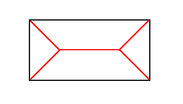
The largest circle that can fit in a corner has zero radius. So we end up with these branches of the MAT skeleton going off towards the corners as the maximal circle for that region gets smaller and smaller.
Shapes like stars have even more corners and would then have even more MAT skeleton branches. Returning a location-specific radius would certainly add more complexity to the SDF. What would we lose if we just... didn't? We could decide that the radius for a rectangle is just the half-length of the shorter side–essentially, the radius of the biggest circle that you could fit inside the body of the rectangle, ignoring the corners.
In general, we could just use the radius of the biggest circle that fits in a shape.
Here's the blur from above running on a rectangle. As the blur increases, you can see some artifacts around the corners. You can kind of make out the shape of the MAT skeleton, actually. It shows up because although the colour change is continuous, the rate of change of the colour change is not, and it changes direction at those spots.
let sdf;
let blur;
function setup() {
  createCanvas(200, 200, WEBGL);
  createP().html('blur').position(0, 185);
  blur = createSlider(0.1, 100, 10, 0.1).position(30, 200);
  sdf = buildFilterShader(rectSDF);
  noLoop();
  blur.input(redraw);
}

function rectSDF() {
  const blurAmt = uniformFloat(() => blur.value());
  filterColor.begin();
  let d2 = abs(filterColor.texCoord - 0.5) * [width, height] - [40, 20];
  let d = length(max(d2, 0)) + min(max(d2.x, d2.y), 0);
  let r = 30
  let c = mix(
    [1, 1, 1, 1],
    [42, 161, 252, 255] / 255,
    1 - (map(d, -blurAmt, blurAmt, 1, 0, true) * min(1, r / blurAmt))
  );
  filterColor.set(c);
  filterColor.end();
}

function draw() {
  clear();
  filter(sdf);
}
This is also one of those points where, knowing we're not looking for photorealism, we can decide whether or not this is good enough. For me, I think this looks good enough for my purposes.
So the MAT direction is cool to know about in theory, but in practice, you can probably just use the largest circle that fits in some part of the shape. If you're doing any SDF unions, you could decide to take the max of the two radii, or if you're doing a smooth union, blend between the two radii with the same blend factor to get some smooth but more local radius values.
Bringing it around town: angular SDFs
So far we've only been talking about SDFs in 2D. I mentioned earlier that it's hard to draw in regular Euclidean 2D and have it work as an environment map. Here's what it looks like if I draw some random circles and try wrap that around a sphere. Make sure you rotate to see the top and bottom of the sphere!
let env;
async function setup() {
  createCanvas(200, 200, WEBGL);
  randomSeed(0);
  const g = createGraphics(1024, 512);
  g.background('#3366FF');
  g.noStroke();
  g.fill(255);
  for (let i = 0; i < 20; i++) {
    g.circle(random(g.width), random(g.height), 100);
  }
  env = g.get();
  g.remove();
}

function draw() {
  background(255);
  orbitControl();
  noStroke();
  texture(env);
  sphere(80);
}
A way to avoid these issues of distortion and edge wrapping is to deal with angles directly. The orientation of a surface is described by a unit vector, its normal. Say we want to put a number of circles around a sphere. If we assign a random direction vector to each one, we determine the angle between one of those circles and the surface normal via acos(dot(n, v)). If we describe the SDF of a circle in terms of angular distance and give it an angular radius, we can use that to draw the circles:
let circles;
async function setup() {
  createCanvas(200, 200, WEBGL);
  circles = buildMaterialShader(circlesShader);
}

function circlesShader() {
  let n = sharedVec3();

  objectInputs.begin();
  n = objectInputs.normal;
  objectInputs.end();

  pixelInputs.begin();
  let nn = normalize(n);
  let minDist = 1000;
  noiseDetail(1);
  for (let i = 0; i < 20; i++) {
    let dir = normalize([
      noise(i, 0),
      noise(i, 50),
      noise(i, 100),
    ] - 0.5);
    minDist = min(minDist, acos(dot(dir, nn)));
  }
  pixelInputs.color = mix(
    [1, 1, 1, 1],
    [51, 102, 255, 255] / 255,
    step(PI * 0.1, minDist)
  );
  pixelInputs.end();
}

function draw() {
  background(255);
  orbitControl();
  noStroke();
  shader(circles);
  sphere(80);
}
Positioning stuff using just the direction is kind of like how we talk about stars in the night sky. The direction vector we used above can be described in two angles: azimuthal and polar. That's also how we can locate stars. Even though stars are three dimensional objects in Cartesian space with us, they're so far away that at a human scale, it doesn't really matter where we move on Earth, it's only the angle to them that makes any difference.
Unlike stars, not everything can be described in just a direction, because they also have an orientation. Let's put a rectangle on the surface of the sphere. In addition to a direction describing its center, we also need a direction describing where "up" is. Here's an example of hard-coding that:
let rectShader;

async function setup() {
  createCanvas(200, 200, WEBGL);
  rectShader = buildMaterialShader(rectShaderFn);
}

function rectShaderFn() {
  let n = sharedVec3();

  objectInputs.begin();
  n = objectInputs.normal;
  objectInputs.end();

  pixelInputs.begin();
  let dir = normalize(n);

  // Direction of rectangle center on sphere
  let center = vec3(0, 0, 1);

  // Build local tangent frame
  let xLocal = vec3(1, 0, 0);
  let yLocal = vec3(0, 1, 0);

  // Chord-space coordinates
  let px = dot(dir, xLocal);
  let py = dot(dir, yLocal);

  // Rotate over time
  let angle = millis() * 0.001;

  let c = cos(angle);
  let s = sin(angle);

  let rpx = c * px + s * py;
  let rpy = c * py - s * px;

  // Rectangle size in chord space
  let half = vec2(0.25, 0.15);

  let q = abs(vec2(rpx, rpy)) - half;
  let d = length(max(q, 0)) + min(max(q.x, q.y), 0);

  pixelInputs.color = mix(
    vec4(1, 1, 1, 1),
    vec4(0.2, 0.4, 1.0, 1.0),
    step(0, d)
  );

  pixelInputs.end();
}

function draw() {
  background(255);
  orbitControl();
  noStroke();
  shader(rectShader);
  sphere(80);
}
It's pretty annoying to do that manually for all possible spots where you might want to place a rectangle, but you can create those local axes automatically. All you need is some vector that isn't in the same direction as the center, and you can use some cross products to create local axes.
let up = abs(center.y) < 0.99
  ? vec3(0, 1, 0)
  : vec3(1, 0, 0)
let xLocal = this.normalize(this.cross(up, center))
let yLocal = this.cross(center, xLocal)
Putting it together: p5.env
Now that we've got the base approach set up, it becomes a matter of making it easy to use. So I've created a library called p5.env. It lets you use p5.strands to code up an environment, and then it applies that light to p5's materials system. It also includes a number of shape helpers that you can use without needing to know the math for them.
The basic structure is the same as any p5.strands shader. You make a function, and then write some code within the .begin() and .end() methods of a hook. The library creates an envColor hook for this purpose. Within it, call let l = envLight(initialColor, envColor.dir, envColor.blur) to create an environment light builder. You can then call methods on it like l.mix(sdf, color), where sdf is something like l.circle(center, radius).
Here's a little example with abstract room ambiance, featuring a fire pit and a window:
let envMat;
let gloss;
async function setup() {
  createCanvas(200, 200, WEBGL);
  envMat = buildEnvMaterial(myEnv);
  createP().html('shininess').position(0, 185);
  gloss = createSlider(1, 200, 150, 0.1).style('width', '125px').position(70, 200);
}

function myEnv() {
  envColor.begin()
  const l = envLight([0, 0, 0], envColor.dir, envColor.blur)
  l.mix(
    l.window(normalize([1, -0.5, 0]), [PI*0.2, PI*0.2], [2, 2], PI*0.05),
    [1, 1, 1.4]
  )
  let flicker = mix(1, 0.6, noise(millis() * 0.001))
  l.mix(
    l.circle(normalize([-0.5, 0.1, 1]), PI*0.05*flicker),
    [2, 1.5, 1] * flicker
  )
  envColor.set(l.get())
  envColor.end()
}

function draw() {
  background(0);
  orbitControl();
  noStroke();
  fill(255);
  specularMaterial(100);
  shininess(gloss.value());
  shader(envMat);
  torus(50, 20, 32, 24);
}
This is showing off a few things. First and foremost, you can create a distinct mood with not that many shapes, as long as you make it easy to program! On a technical level, this is also showing how we can use different SDFs to create interesting light components, like the window pane. It also shows how we can animate elements: both the size and the brightness of the fire are animated. And speaking of brightness, all of the lights in this scene exceed the usual 0-1 range of colour values, allowing them to punch through an otherwise not that reflective glossy coat on the torus.
Here's another example showing an animated day/night cycle:
let envMat;
let pano;
let gloss;
async function setup() {
  createCanvas(200, 200, WEBGL);
  envMat = buildEnvMaterial(myEnv);
  pano = buildEnvPanorama(myEnv);
  createP().html('shininess').position(0, 185);
  gloss = createSlider(1, 200, 150, 0.1).style('width', '125px').position(70, 200);
}

function myEnv() {
  envColor.begin()
  let sunAngle = millis() * 0.0003
  let sunDir = normalize(vec3(-0.25 * sin(sunAngle), cos(sunAngle) * -1, -1))
  let daylight = map(dot(sunDir, [0, -1, 0]), -1, 1, 0, 1)
  let ground = [86, 73, 67] / 255
  ground *= map(daylight, 0.2, 0.6, 0, 1, true)
  let nightSkyColor = vec3(0.08, 0.08, 0.25)
  let sunColor = mix(nightSkyColor, vec3(4.0, 3.5, 2.0) * 0.7, daylight)
  let skyColor = mix(nightSkyColor, vec3(0.5, 0.75, 1.0), daylight)
  let horizonColor = mix(
    mix(nightSkyColor, vec3(0.5, 0.2, 0.45), map(daylight, 0.2, 0.5, 0, 1, true)),
    vec3(0.3, 0.55, 1.0) * 0.7 + 0.4,
    daylight
  )
  let sky = envGradient(envColor.dir, [0, -1, 0], envColor.blur,
    { t: PI * 0.3,  color: skyColor },
    { t: PI * 0.55, color: horizonColor },
  )
  let l = envLight(sky, envColor.dir, envColor.blur)
  l.mix(l.circle(sunDir, PI * 0.04), sunColor)
  l.mix(l.circle([0, 1, 0], PI * 0.5), ground)
  envColor.set(l.get())
  envColor.end()
}

function draw() {
  background(0);
  pano(PI * 0.01);
  orbitControl();
  noStroke();
  fill(255);
  specularMaterial(100);
  shininess(gloss.value());
  shader(envMat);
  torus(50, 20, 32, 24);
}
This obviously doesn't look as realistic as an actual skybox shader simulation, but it does give a fair amount of artistic control. The sky is just a gradient with a few colour stops whose values get tweaked over time. It is really easy to replace colours to add exaggeration or to create an alien green sky and such. This also is showing how you can create a background panorama using the same environment light.
While we're showing off panoramas, here's a cloudy sky. To simulate blur of the noise texture, octaves of noise are slowly removed as the blur radius increases.
let envMat;
let pano;
let gloss;
async function setup() {
  createCanvas(200, 200, WEBGL);
  envMat = buildEnvMaterial(myEnv);
  pano = buildEnvPanorama(myEnv);
  createP().html('shininess').position(0, 185);
  gloss = createSlider(1, 200, 150, 0.1).style('width', '125px').position(70, 200);
}

function myEnv() {
  envColor.begin()
  let sky = [0.5, 0.75, 1]
  let l = envLight(sky, envColor.dir, envColor.blur)
  let t = millis() * 0.00005
  let cloudySky = mix(sky * 0.5, vec3(1), l.noisePlane([0, 1, 0], 0.5, 0.4, { offset: [t, t * 0.4] }))
  l = l.mix(l.circle([0, -1, 0], PI/2), cloudySky)
  l = l.mix(l.circle([0, 1, 0], PI/2), [86, 73, 67] / 255)
  envColor.set(l.get())
  envColor.end()
}

function draw() {
  background(0);
  pano();
  orbitControl();
  noStroke();
  fill(255);
  specularMaterial(100);
  shininess(gloss.value());
  shader(envMat);
  torus(50, 20, 32, 24);
}
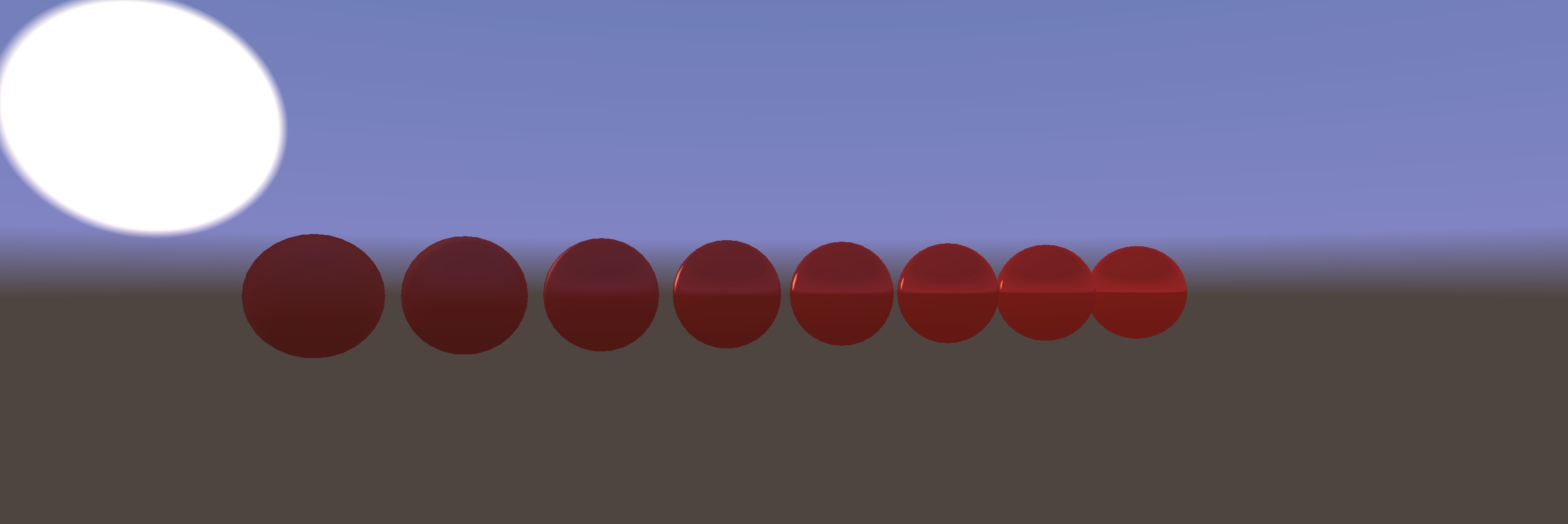
p5.env taps into the standard p5 material system. Here's what a red sphere looks like in the above environment, where going to the right increases shininess, and going down shifts from being glossy to being metal. As always, click and drag to orbit.
I'm probably going to be using this from now on in scenarios where I would normally reach for imageLight() and then spend time trying to find an image close enough to what I want on PolyHaven or something like that. Let me know if this works for you too, I'd like to see what you make!
Addendum: p5.strands add-ons
This is the first time I've tried making a p5.js add-on that specifically creates a new base shader for p5.strands. The good news is that it works! You can look at the source code for p5.env on GitHub to see how it's done.
There are a number of things that could be smoothed out though:
- The only way to make a shader with now hooks is to write GLSL or WGSL strings. The API for this is not super well documented. While it's also possible to write a different version for WebGL and WebGPU, it's slightly nontrivial how to do so (for example, the RendererWebGPU class may not exist at all if the WebGPU addon is not loaded, so patching methods onto it without checking for its existence first may throw an error.) Currently, p5.env is WebGL-only for this reason. We can definitely make an addon API easier for this!
- To work best with p5's existing shaders, you really want to extend the built-in ones rather than make something completely from scratch. This is mostly possible, but requires currently-undocumented knowledge of how to do so via the non-strands shader hook API. A tutorial could fix this though.
- ...but also sometimes you specifically want to omit parts of the default shaders. Currently p5.env still includes all the GLSL for imageLight and Phong lighting even though they will go unused. We could maybe add some precompiler flags to make it easier to conditionally omit things.
- Library code is not transpiled like regular p5.strands functions are: only the code directly in the function you pass to a build*Shader method gets transpiled. That means you can't create vectors with JavaScript array notation, and you can't use operator overloading. The library source code contains the line:
...since it can use neither ternaries nor comparators. On the plus side, it's helpful having the ability to use JavaScript control flow as a macro: p5.env inlines the logic for blurring a gradient with multiple colour stops rather than doing dynamic loops.let up = p5.strandsTernary( this.abs(center.y).lessThan(0.99), this.vec3(0, 1, 0), this.vec3(1, 0, 0) )
If you are interested in making p5.strands add-ons too, or in improving the add-on API for future developers, join the p5.js Discord server and let me know in the p5.strands channel!